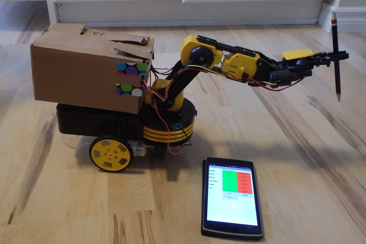
Create a mobile robot arm that you can control from an Android smart phone.
We found a used robot arm (OWI-535) on Kijiji, but you could buy a new one for $30-$60. We then mounted it on an Arduino car chassis ($20) with some duct tape. Luckily the OW-535 robot arm has all its wiring exposed and it comes with a good wiring document.
Parts
For this project we used:
- 1- OWI-535 robot arm
- 1- Car chassis ($17)
- 1- Four motor Arduino shield ($10)
- 1- Two motor Arduino shield ($10)
- 1- JY-MCU Bluetooth module ($7)
- 1- Arduino Mega
- Duct tape, jumpers and 4 alligator clips
- 1- Small USB charger
- 1- Small Box (to house all the components)

Wiring
The biggest challenge is to control the 5 robot motors and 2 wheel motors. For this we used an Arduino Mega and 2 motors shields. Depending on the motor shields that you use you probably won’t be able stack the motor shields. We stacked one motor shield and we had the second motor shield floating.

Some of the key wiring connections were:
- Mega Pin 44 -> Floating Motor Shield pin 4
- Mega Pin 45 -> Floating Motor Shield pin 5
- Mega Pin 46 ->Floating Motor Shield pin 6
- Mega Pin 47 -> Floating Motor Shield pin 7
- Mega Pin 5V -> Floating Motor Shield pin 5V and VIN
- Mega Pin 19 RX1 -> Bluetooth module TX
- Mega Pin 18 TX1 -> Bluetooth module RX
To power this project we found that a portable USB charger was enough. If however you find that a USB charger does not deliver enough power the OWI-535 robot arm has a built in power pack with exposed power connections.
The motor terminals on the car chassis are a little fragile, so rather than soldering wires we used alligator clips. We also duct taped the wires under the car chassis to keep them secure.
The Arduino wiring was pretty ugly so we stuffed all the loose components into a small box. The box was duct taped to the back of the robot arm, and 2 cuts were made to feed the wires through.

Code
For the Arduino code you’ll need to add the appropriate motor libraries. For our motor shields we used the Adafruit V1 motor shield (https://github.com/adafruit/Adafruit-Motor-Shield-library).
Because the first motor shield blocked the RX0/TX0 pins, we used RX1 and TX1 on pins 19 and 18. For the Bluetooth communications it meant the Serial1 was used in the Anduino code instead of Serial.
For our commands we used:
- 0 = Hand open (motor 1 forward)
- 1 = Hand closed (motor 1 backward)
- 2 = Wrist down (motor 2 forward)
- 3 = Wrist up (motor 2 backward)
- 4 = Elbow down (motor 3 forward)
- 5 = Elbow up (motor 3 backward)
- 6 = Shoulder up (motor 4 forward)
- 7 = Shoulder down (motor 4 backward)
- g = Go forward (pins: 44/46=HIGH, 45/47=255)
- s = Stop (pins: 44/46=HIGH, 45/47 =0)
- r = Right turn (pins: 44/46=HIGH, 45=0, 47 =255)
- l = Left turn (pins: 44/46=HIGH, 45=255, 47 =0)
- b = Go backward (pins 44/46= LOW, pins 45/47 =255)
- o = Light ON, (pin 50 = HIGH)
- f = Light OFF, (pin 50 = LOW)
Our final Arduino code is:
//
// Bluetooth control of a mobile robot arm
//
#include

char inByte;
// Define remapped pins for 'floating' motor shield
int E1 = 45;
int M1 = 44;
int E2 = 46;
int M2 = 47;
int LIGHTpin = 50;

// DC motor on M1
AF_DCMotor motor1(1); // hand
AF_DCMotor motor2(2); // wrist
AF_DCMotor motor3(3); // elbow
AF_DCMotor motor4(4); // shoulder


void setup() {
 pinMode(M1, OUTPUT);
 pinMode(M2, OUTPUT);

pinMode( 19, INPUT_PULLUP ); // For better Bluetooth stability
 Serial1.begin(9600);
 Serial1.println("Robot Commands");
 Serial1.println("Menu...");
 Serial1.println("Enter: 0-7 for robot arm, g/s/l/r/b for wheels ");
}

void loop() {

 if (Serial1.available() > 0) {

// read the incoming byte:
 inByte = Serial1.read();
 if (inByte == '0') { runmotor(motor1,FORWARD); }
 if (inByte == '1') { runmotor(motor1,BACKWARD); }
 if (inByte == '2') { runmotor(motor2,FORWARD); }
 if (inByte == '3') { runmotor(motor2,BACKWARD); }
 if (inByte == '4') { runmotor(motor3,FORWARD); }
 if (inByte == '5') { runmotor(motor3,BACKWARD); }
 if (inByte == '6') { runmotor(motor4,FORWARD); }
 if (inByte == '7') { runmotor(motor4,BACKWARD); }
 if (inByte == 'g') { runwheels(HIGH,HIGH,255,255); }
 if (inByte == 's') { runwheels(HIGH,HIGH,0,0); }
 if (inByte == 'r') { runwheels(HIGH,HIGH,0,255); }
 if (inByte == 'l') { runwheels(HIGH,HIGH,255,0); }
 if (inByte == 'b') { runwheels(LOW,LOW,255,255); }
 if (inByte == 'o') { digitalWrite(LIGHTpin, HIGH); }
 if (inByte == 'f') { digitalWrite(LIGHTpin, LOW); }
 }
}
//--------------------------------------------------
void runwheels (int M1dir,int M2dir,int E1speed, int E2speed) {
 // For control of wheels direction and speed
 digitalWrite(M1, M1dir);
 digitalWrite(M2, M2dir);
 analogWrite(E1, E1speed);
 analogWrite(E2, E2speed);
}
//--------------------------------------------------
void runmotor(AF_DCMotor themotor, int direction) {
 // Robot Arm motor control
 themotor.setSpeed(250);
 themotor.run(direction);
 delay(250);
 themotor.run(RELEASE);
}
Android App
MIT’s App Inventor is free and it’s a great way to quickly make Android apps: http://ai2.appinventor.mit.edu/.
For this app we used:
- 1 TableArrangement
- 1 Listpicker
- 15 Buttons
- 7 Labels
- 1 BluetoothClient (non-visible)

A TableArrangement component with 3 columns and 11 rows is used to position all of the buttons and labels. After a component is positioned into the table, select the component and then use the Properties window to change its text, color, or sizing. The Components window is used to rename the component.
In the Blocks screen, blocks are dragged from the left Blocks section to the main viewer section. The following key blocks were used:
- when Screen1.Initialize. This is called when the app is opened and it will show a list of all the phone’s paired Bluetooth device. This list is generated by connecting the blocks: BluetoothClient1.AddressesAndNames to set ListPicker1.Elements
- when ListPicker1.BeforePicking. This block is called after the JY-MCU Bluetooth module (typically HC-06) is selected. Inside this block ListPicker1.Selection is an input to the Call BluetoothClient1.Connect block.
- when .Click. This block is called when a “command” button is clicked. This block will send the required Bluetooth text command, so for example “g” is sent to go forward, and “s” is sent to stop.

The full AppInventor code is:

Once all the logic is created, you can download the app (APK file) or use a QR quick code to put it on your phone.

The final step is to power up your Arduino project. When you do this the JY-MCU Bluetooth module will start to blink. This is telling you the module is ready to pair with your phone. On your phone’s SETUP->BLUETOOTH SETTINGS scan for new devices and you should see the JY-MCU Bluetooth module (it’ll probably be called HC-06). The pairing code is: 1234.
Now you are ready to open your new Android app. A dialog will ask you which device to connect to. Select your HC-06 device.

For this point on you will be able to control the robot with your phone.

