Cardstock is an Python GUI builder that is focused on making it easy for new Python programmers to create card or form based applications. I was a little sceptical at first but I thought that I’d try using Cardstock with a typical Raspberry Pi project.
This blog shows the steps that I went through to create a Raspberry Pi GUI app that shows BME280 sensor data.
Getting Started
The first step is to install the cardstock Python library and it’s dependencies:
pip3 install cardstock
The biggest difference between cardstock and a typical Python project is that cardstock has a graphic creation environment with an embedded event editor where the Python code is inserted. This means there are no external Python (.py) files, instead the code is embedded within the cardstock (.cds) file.
To start cardstock, at the command line enter: cardstock. The IDE has a left panel for design, and a object configuration panel, and an event code panel.
BME200 Sensor Project
A BME280 Python sensor library in stalled by:
pip3 install bme280pi
For the sensor data, I wanted to have the results shown in vertical bars. My first pass only had 1 bar with a top value, and a bottom label. I used 2 rectangles, an outer for a frame, and a fill inner bar with a height of 200. Once I was happy with the first bar I grouped everything together and then made 2 copies.
After I tweaked each of the objects with an _1, _2 or _3 and I edited the colours and custom descriptions I added the Python code.
By clicking on the card background, the card’s on_setup(self) code window can be accessed.
Python libraries would be typically be defined in the on_setup function.
Rather than putting all the sensor refresh code in the on_setup I created an on_message function. (Use the +Add Event button for this). I would have rather created a custom get_sensor_data() function, unfortunately cardstock didn’t seem to support the creation of custom functions.
Note: Communications between functions is done via messages
To manually refresh the card a Refresh button was added. A button press would issue an on_click event. Like the card on_setup function a: card.send_message(‘refresh’) function is also called to refresh the sensor data.
The running app looked like:
Summary
For new Python coders Cardstock offers a nice easy programming environment. The integration between drawing objects and coding Python event, ties things together cleanly. I believe that this is a great package for kids to learn and play with.
As an experienced user, however, I found that Cardstock was missing a lot of widgets (especially charting, tables, and timers) that I’m used to having.
As a continuation to this project more cards could be added to show historical data and webcam video feed.
If you want to build some fun Pi projects, but are still working on your Python skill, then mixing Node-Red with Python might be a good option for you.
Node-Red is a low-code application that is extremely powerful for the creation of Raspberry Pi robotic and Internet of Things (IoT) projects. Node-Red has a rich set of libraries to create simple drag-and-drop logic flows.
By default Node-Red custom scripting is done in Javascript, however Python can also be used. For Python users this offers them a platform to play and learn Python basics while taking advantage of the Node-Red’s low-code interface to manage scheduling and web dashboards.
There are many cases where Raspberry Pi features are only available in Python, so even die-hard Node-Red users could benefit with knowing how to integrate Python into their projects.
In this blog I’ll look at two examples that mix Python and Node-Red. The first will create web dashboard to drive a Raspberry Pi rover. The entire project will only use two Node-Red widgets, where one of the widgets uses Python script within the Node-Red environment. The second project will create an IoT page that shows temperature and humidity data from an BME280 sensor.
Getting Started
Depending on your Raspberry Pi image, Node-Red may already be installed. If not, see the Node-Red documentation or your Pi image for custom installation directions.
There are some excellent dashboard components that can be used to create some light-weight web interfaces. For this blog, I’ll be using the Button State flow. This widget can be used to create an array of buttons. To install this component go into the Manage Palette menu item, click on the install tab, and then search for ui-button.
The next important step is to add a Python enabled widget, there are a few choices. I chose the python-function-ps component because it’s been recently updated, however the other two choices worked on my test projects.
Being able to use Python instead of Javascript in Node-Red is an extremely useful features, however it’s not bulletproof and some care will be needed when you’re using some advanced Python libraries.
In the next section I’ll use these two widgets to control a Raspberry Pi rover.
Creating a Raspberry Rover
There are many approaches to creating a car or a rover with a Raspberry Pi. For this project I used:
A 2-motor car chassis (~$15)
Portable battery (5V, 3 Amp output ~$30)
Raspberry Pi with a motor shield
4 alligator clips, and 4 jumper wires
some elastic bands and duct tape
For a Raspberry Pi 3 and 4 the portable battery needs to output 3A. If you are using an other PI 1/2 you can use a standard 2.1A phone charger.
Due to the power draws it is not recommended that you connect motors directly to a Raspberry Pi, luckily there are quite a few good motor or automation shields available (~$25). If you’re feeling adventurous you can build your own motor shield with a L293D chip for ~$2. On this project, I used an older PiFace Digital module which is has good Python support, but weak Node-Red functionality.
The 2-motor car chassis usually come without any wiring on the motors. For a quick setup I used a combination of alligator clips and jumper wires to connect the motor terminals to the Pi motor shield. A couple of strips of duct tape is useful for holding the wires in place. Finally elastic bands can keep the portable battery and the Raspberry Pi attached to the chassis.
To test the hardware setup, I found it best to keep the car chassis raised up with the wheels off the ground. This step allows you to use a standard power plug without killing your battery before you’re ready to play. You may have to do some playing with the wiring to ensure the motors are both turning in the required direction.
The first software step is to install your motor’s Python library. (Note: this step will vary depending on your motor shield). For my hardware the PiFace library is installed by:
pip install pifaceio
At this point, it’s important to test the hardware directly from Python. Check your hardware documentation for some test code to turn on and off a motor.
To test a single motor with Python within Node-Red, three flows can be used: an inject, a python-function-ps, and a debug.
The inject flow is used to create a message payload with either a numeric 0 or 1, to stop or start a motor.
In the python-function-ps flow the incoming Node-Red message (msg) is accessed as a Python dictionary variable. Below are some Python examples to read and manipulate the Node-Red message.
# get the message payload
themsg = msg['payload']
# set the payload
msg['payload'] = "Good Status"
# create an item in the message structure
msg['temperature'] = 23.5
# clear the entire message
msg.clear()
For the PiFace library, my code needed to do a write_pin command to set a specific pin, and then a write command outputs the request states for all the pins.
pin = 0
# Pass the msg payload as the pin state
pf.write_pin(pin,msg["payload"])
pf.write()
A debug flow will show if there are any problems in the Python code.
Once the basic testing is complete, then next step is to define a Node-Red dashboard that creates an array of buttons to control the rover.
The Node-Red logic for this project only requires the two new widgets that were installed earlier.
The Button State widget is edited by double-clicking on it. Multiple buttons can be added with custom labels, payloads and colors.
A simple two character string is used for the button’s message payload, with the first character being the LEFT motor state, and the second being the RIGHT motor state. A FORWARD command will set both the LEFT and RIGHT motors to 1, with a payload of 11. It’s important to note, that to turn LEFT, the LEFT motor needs to be turned off and the RIGHT motor needs to run, and visa versa for turning RIGHT.
Inside the python-function-ps flow (see below), the Python pifaceio library is imported (line 4) and a pf object is created (line 5). Next the passed button payload is parsed to make two variables, the LEFT and the RIGHT requested motor state (lines 8-9). The final step is to write to the motor states (lines 11-12).
#
# Set PiFace Digital Pins
#
import pifaceio
pf = pifaceio.PiFace()

# Get the Left and Right requested state
LEFT = int(msg["payload"][0])
RIGHT = int(msg["payload"][1])

# Set the left and right pin motor values
#   the left motor is on pins 0 and  right on pin 1
pf.write_pin(0,LEFT)
pf.write_pin(1,RIGHT)
pf.write()

return msg
A debug flow isn’t required but it can be useful to verify that the Python code completed cleanly.
The image below shows Rover with PiFace Digital module mounted on a Pi 1 with the Node-Red dashboard.
The interesting thing about this first project, is that it shows how lean the logic can be if you mix Python with the right Node-Red components, (only 2 flows!).
If the motor shield is based on the L293D chip set, then buttons and pins could be added for going is backward directions.
Easing into Python
There is an excellent selection of Raspberry Pi Python starter projects that can be done. Communicating with I/O, motors or sensor is always a good place to start.
The second example will look at getting temperature and humidity data from a BME280 sensor (~$5). The gathering of the sensor data will be done in Python, then the real time scheduling and the web dashboard will be created in Node-Red.
The BME280 sensor wires to the Pi using I2C (Inter-Integrated Circuit) connections. The SDA (Serial Data) and SCL (Serial Clock) are on Rasp pins 3 and 5.
The first step in the project is to enable I2C communications, and then install a Python BME280 library:
This Python code can be tested in Node-Red with inject and debug flows.
There is a slight modification to the code (lines 17-21) where instead of doing a print statement, the sensor results are passed to the dictionary msg variable. The debug flow is defined to show the complete message, so in the debug pane it is possible to see all the sensor results.
The next step is to show the results in a web pages, and this is done with the addition of two new widgets. The first new is an old style mercury thermometer widget (ui-widget-thermometer), and the second is a scheduler (bigtimer). Note: it is also possible to include the Node-Red BME280 component for a comparison check.
The final application uses the same Python code, but a bigtimer widget schedules its execution. The bigtimer has excellent scheduling functionality, but to keep things simple the middle output can be used to sends out a pulse every minute.
The thermometer widget shows the temperature value which is the payload message from the Python script. A chart widget also reads the temperature and is configured to a 2-hour line plot.
A change component is needed to move the humidity to the payload, and this allows a second chart to show the humidity in a bar chart.
Below is a picture of a Raspberry Pi with a BME280 sensor and the Node-Red Dashboard.
Calling External Python Scripts
I found a few cases where the python-function-ps widget crashed. For me this occurred with hardware specific libraries like pyusb.
The build-in Node-Red exec component can be used to run any external program.
Below is an example to pass a Javascript timestamp into a Python program which outputs the date/time as a string without milliseconds.
The exec block is configured to append the upstream msg.payload to the command.
The external Python script uses the sys library with the argv array to read in the passed payload. Python print statements become the top output pin (stdio) that is the msg.payload for downstream components.
Below is the test Python script used to read the Node-Red payload and output a date/time string.
#
# test.py - interface with Node-Red
#           Convert Javascript timestamp to string
import sys
from datetime import datetime

# Print out the timestamp as a string
if len(sys.argv) > 1:
    passedtime = int(sys.argv[1])
    # Strip out milliseconds
    timestamp = int(passedtime/1000)
    print(datetime.fromtimestamp(timestamp))
Summary
Python scripting in Node-Red offers new user programmers a great way build some fun applications without getting too bogged down.
If you’re like me, you might have some old Raspberry Pi B+ or Pi 2 modules kicking around collecting dust. By today’s Pi 4 standards, these older modules can be a little painful to work with. Luckily you have some options to improve the performance of your old Pi hardware.
DietPi is a highly optimised lightweight version of the Debian OS that focuses on running Raspberry Pi’s and other single board computers at their maximum potential. For example on a Pi 2 running the Raspberry Pi OS Lite (32-bit), DietPi boasts:
27% faster boot up time,
28% less RAM usage,
and 50% less background processes
In this blog I wanted to introduce DietPi with an installation on an old Raspberry Pi B+ system. For my testing I will do some a head-to-head comparisons with Raspberry Pi OS Lite (32-bit) and a WiFi connection.
Before you jump in and start to reload our old Pi models, I just want to pass on my key take-aways:
Raspberry Pi OS’s installation is graphical, so it’s much slower, but it’s easier to use.
the DietPi WiFi setup was a little confusing to use the first time
DietPi boot time on WiFi is only about 17% faster (not the advertised 27%)
DietPi runs with noticeably lower CPU load
DietPi offers an installation app with optimised software packages
DietPi being Debian is close enough to the Raspberry Pi OS that it feels very familiar at the command line.
DietPi makes a great Pi server. If you’re looking for a Pi client desktop, the standard Raspberry PI OS might be a better fit because of it’s guides and large installed base.
Getting Started
The Raspberry Pi Imager can be used to install both standard Pi Images and other 3rd party images. The DietPi Download page has images for many of the mainstream single board computers.
To create a bootable SD image with DietPi, select the “Use Custom” option on the Pi Imager.
One of the major differences between the Raspberry Pi OS and DietPi installations, is that DietPi goes directly into a command line interface with text menus. The Raspian/PI OS desktop interface is slick, but with older hardware it can be painfully slow.
If you using a wired Internet connection your DietPi setup will be be very straight-forward. My setup required a WiFi connection, so I needed to do a few extra steps.
At first time boot-up, DietPi will present a DietPi-Config menu page.
This configuration page offers all the key Pi options. To connect to a wireless access point, select the “Network Options: Adapters” line.
Then select the WiFi option, and configure your SSID and password information for you wireless connection.
After the WiFi connection is configured, a: Test: Run internet connection testoption needs to done.
A restart of the system will offer information about the base system and the main configuration tools
Adding Software to DietPi
As mentioned earlier, DietPi is based on Debian, so the same apt (Advanced Package Tool) that Raspberry Pi uses can install software.
A selection of DietPi optimised software packages can be loaded using the DietPi-Software utility.
The Browse Software tool shows grouping of common packages:
My Test Setup
For my test setup I wanted to ensure that some key items could run with DietPi. Everyone will have their own list of essential functions, for me I need:
Python3 with GPIO/I2C support
Support for old Raspberry Pi B+ hardware
Node-Red support
My project hardware included an older PiFace Digital Top and a USB hub with a WiFi adapter.
DietPi has no problems with either GPIO (General Purpose Input /Output), I2C (Inter-Integrated Circuit) or Node-Rede. All of these connections are included in the Hardware Projects section of the DietPi-Software application.
Pi B+ Performance Differences
The Raspberry Pi Lite OS image is considerably larger than the Dietpi image ( 364MB versus 207M), and this footprint difference is noticeable in the following areas:
Feature
Raspberry Pi Lite
DietPi
Difference
Image Size
364MB
207MB
43% smaller
Boot Time
59s
49s
17% faster
Free Memory
266k
324k
22% more
Cache
107k
76k
29% smaller
Running tasks
91
63
30% less
Raspberry Pi Lite vs DietPi on a Raspberry Pi B+
The biggest performance difference that I found was in load average. The uptime command will show 1-m, 5-min and 15-min load averages. The lower the number the better.
After letting the Raspberry Pi’s stabilise for 20-minutes I ran uptime on both systems and the numbers were:
OpenWRT is an open source firmware that can be loaded on many commercially available routers. The firmware offers an upgrade path for older or obsolete hardware and customization/advanced features for newer equipment.
With OpenWRT’s small footprint (176MB vs. 1.7GB Raspbian image), it’s ideal for older Raspberry hardware where speed and memory usage is an issue.
For small home and office projects OpenWRT will offer some interesting networking solutions, such as making the Pi into an access point or using it as a wireless LAN bridge. However it’s important to note that the Raspberry Pi WiFi hardware will not offer the same performance as you’ll find on dedicated routers.
In this blog I documented my notes on getting an old Raspberry Pi Model B up and running with OpenWRT. I also tried to explain how to install many of the common Pi functions (loading software, GPIO, I2C…)
Pro’s and Con’s
Before jumping into a Pi OpenWRT project it’s useful to know where it stands versus the default Raspberry Pi OS.
Some of the OpenWRT advantages (over Raspbian/Raspberry PI OS) include:
It’s fast. It was designed to run on lower end CPU’s with limited memory
Network focused
Fast bootup
Smaller OS footprint so even older 4 GB SD card be used (2GB is possible but may not be able to load many software packages).
Some OpenWRT limitations:
No X-window desktop.
System setup isn’t streamlined like the default Raspberry PI OS (there’s no raspi-config)
Default installation is quite bare, so you need to manually load packages (even Bash and Nano)
Some packages could be a challenge to install (for example Node-Red)
Getting Started
Despite the fact that OpenWRT is designed to run on routers, in many ways its easier to play with on a Raspberry Pi. Some of the benefits of using a PI are:
you can’t ‘brick’ the Raspi. (I’ve come close many times playing with home routers)
SD/microSD card have considerably more space than most home routers. (This was in issue for me with older routers).
Pi has an HDMI connection so you can work directly on the PI (good for getting started)
You can use the standard Raspi imager to install OpenWRT on an SD card. For Linux systems the imager can be installed by:
sudo apt update && sudo apt install rpi-imager
After an SD card has been loaded up there are several way to get an OpenWRT system up and running. Below are the steps that I used.
1. Connect a monitor and keyboard to the Pi
Let it boot up and then go to the command prompt, and setup an static LAN address:
# Enter your own static IP. Note: change the gateway/DNS for your setup
uci set network.lan.proto="static"
uci set network.lan.ipaddr="192.168.0.140"
uci set network.lan.netmask="255.255.255.0"
uci set network.lan.gateway="192.168.0.1"
uci set network.lan.dns="192.168.0.1"
uci commit network
If you able to see IP addresses on your LAN you can simple do:
# Set Pi for DHCP and then check its address
uci set network.lan.proto="dhcp"
uci commit network
2. Hardwire Pi to Your LAN
Connect the 100BaseT port of the Pi to your LAN and then reboot the module.
From a laptop you now can use OpenWRT’s Web Interface or you can use the secure shell (ssh) command line interface.
I like the ssh option to get started because I can paste in groups of commands. To get started with ssh (with my static IP) :
$ ssh root@192.168.0.140


BusyBox v1.35.0 (2023-01-03 00:24:21 UTC) built-in shell (ash)

  _______                     ________        __
 |       |.-----.-----.-----.|  |  |  |.----.|  |_
 |   -   ||  _  |  -__|     ||  |  |  ||   _||   _|
 |_______||   __|_____|__|__||________||__|  |____|
          |__| W I R E L E S S   F R E E D O M
 -----------------------------------------------------
 OpenWrt 22.03.3, r20028-43d71ad93e
 -----------------------------------------------------
=== WARNING! =====================================
There is no root password defined on this device!
Use the "passwd" command to set up a new password
in order to prevent unauthorized SSH logins.
--------------------------------------------------
root@OpenWrt:~#
3. Install Your Required Software
The default OpenWRT installation is extremely bare, so will probably need a number of basic packages.
OpenWRT uses opkg to install software. (Note: apt and apt-get are not supported in OpenWRT).
As a bare minimum I like to load:
# Install some software, but update list first
opkg update
# Install Bash, nano editor
opkg install bash nano
# For Python projects install the base Python3 and pip
opkg install python3 python3-pip
# For Pi GPIO projects
opkg install  gpioctl-sysfs gpiod-tools
If you are planned to do some projects on your Raspberry Pi adding Bash, Python, and GPIO hardware support will be useful.
LuCI – OpenWRT Web Interface
After the system was up and running, the LuCI web interface can be used to setup other features such as networking interfaces and custom software. Many of the software packages also include additions to a LuCI web add-on.
From the LuCI interface you are easily see how much memory and disk space is available. It is important to check this screen if you’re planning on loading a large number of software packages.
Setup a USB WiFi Adapter
For Raspberry Pi models 3 and 4 OpenWRT will identify their built-in WiFi hardware, however for earlier models or projects where you want to use a USB WiFi adapter you’ll need to do this step.
On OpenWRT the configuring of USB devices has to be added manually. The first step is to install the USB utilities package:
# Update the package list
opkg update
# Add USB Utils (has lsusb)
opkg install usbutils
Once usbutils in added, the lsusb command will show information about the connected USB devices (Note: drivers still need to be loaded). For my Raspberry Pi B setup with an old Realtek WiFi adapter my output was:
root@OpenWrt_Pi1:~# lsusb
Bus 001 Device 004: ID 0bda:8189 Manufacturer_Realtek RTL8187B_WLAN_Adapter
Bus 001 Device 003: ID 0424:ec00
Bus 001 Device 002: ID 0424:9512
Bus 001 Device 001: ID 1d6b:0002 Linux 5.10.176 dwc_otg_hcd DWC OTG Controller
From this listing I can see that I need to search for a RTL8187B_WLAN_Adapter. The Luci Web Interface can be used to find and install the required network driver.
Once the USB WiFi adaptor is enabled, there are several different wireless arrangements that can be used, some of the more common setups would be:
Wireless application node, (like a typically Raspberry Pi setup)
Access point node, to setup your own custom network
Wireless bridge, to extend an existing wireless network
For a simple wireless application node, go into the LuCI web interface Network->Wireless menu option, and then select your radio and scan for a wireless network. After a SSID (a wireless connection) is configured, select Edit to add the network information.
Ensure that you select both lan and wwan, by doing this you will be able to remotely access the Pi node via both wireless and wired connections.
Using SFTP and FileZilla
Remotely working a OpenWRT can be a little challenging if you are only using the SSH and Luci web interface. A Secure File Transfer Protocol (SFTP) server package can be used to greatly improve editing and saving of configuration and coding files.
The OpenSSH-FTP server package is installed by:
# For remote work add an SFTP server
opkg update
opkg install openssh-sftp-server
After this software has been loaded a graphical SFTP client package like FileZilla can be used on a laptop.
FileZilla allows for an easy visual interface for remote coding and maintenance. Below is an example of FileZilla connecting into an OpenWRT Raspberry Pi node. A file association on FileZilla has been setup to link py files to the basic Python Idle editor.
A Raspi 3 Example
I wanted to do a more complete Pi functions test. For this project I used Pi 3 because I wanted to test controlling the USB power. (Note: USB power control is only available on Pi 3 and 4).
My goal was to play with GPIO, I2C and USB power. In the final project I used OpenWRT’s built-in uhttpd web server to show the results.
Below are some of the individual steps that I did to get things running.
GPIO Setup
The base GPIO packages need to loaded:
 # update list of available packages
opkg update
opkg install  gpioctl-sysfs gpiod-tools
After the basic GPIO software is installed Raspberry Pi pin can be read to and written to in Bash (or ash which is the default OpenWRT shell).
Before a GPIO pin can be used it needs to defined. The tee command can be used to create a gpio definition with all the required files, for example:
# Create a gpio4 definition
echo 4 | tee /sys/class/gpio/export

# Show the file structure
ls /sys/class/gpio/gpio4
active_low  direction   power       uevent
device      edge        subsystem   value
A example to create a GPIO definition, then to write to the pin and read the value back is:
# Define the pin as an output
echo "out" > /sys/class/gpio/gpio4/direction
# Set the pin on (1)
echo 1 > /sys/class/gpio/gpio4/value
 # Read the pin value
cat /sys/class/gpio/gpio4/value
1
If you are doing some playing around and you want to remove a gpio definition then write to the unexport file:
# Remove GPIO4
echo 4 | tee /sys/class/gpio/unexport
I2C Setup
To get the I2C setup working the Raspberry Pi I2C chipset driver and the I2C tools need to be loaded:
# Update the opk list. This needs to be done once after a power up
opkg update
opkg install kmod-i2c-bcm2835 i2c-tools
The next step is to edit the file: /boot/config.txt
nano /boot/config.txt
At the bottom on the file add three dtparam lines:
################################################################################
# Bootloader configuration - config.txt
################################################################################

################################################################################
# For overclocking and various other settings, see:
# https://www.raspberrypi.org/documentation/configuration/config-txt/README.md
################################################################################

# OpenWrt config
include distroconfig.txt

[all]
# Place your custom settings here.
dtparam=i2c1=on
dtparam=spi=on
dtparam=i2s=on
Once the file is edited the system needs to be rebooted. After this I2C devices can be connected up. To check that the I2C addresses for wired devices use the i2cdetect command:
(Note: for this i2cdetect example, addresses 28 and 48 were on from the Pimoroni Explorer HAT, and address 77 was a BME280 sensor).
Typically the next step is to install Python with pip and then any required I2C device library. For this project I was using a BME280 temperature/humidity sensor.
BME280 Sensor Setup
Each sensor will have its own particular library, however you’ll probably need the python3-smbus support.
The Python bme280 library also has a Bash interface, so to get the data from I2C address 77:
# Get the BME280 sensor data from address 0x77
read_bme280  --i2c-address 0x77

1005.19 hPa
  38.38 %
  19.25 C
Control USB Power
Controlling the USB power is not something that is done very often. Some use cases might be: USB fans and lights or resetting an Arduino controller that a Pi is powering/connected to.
For this feature you’ll need to run:
opkg install usbutils uhubctl
The lsusb command will show which smart USB devices are connected, it will not show simple hardware like USB fans and lights.
lsusb --tree
/:  Bus 01.Port 1: Dev 1, Class=root_hub, Driver=dwc_otg/1p, 480M
    |__ Port 1: Dev 2, If 0, Class=, Driver=hub/5p, 480M
        |__ Port 1: Dev 3, If 0, Class=, Driver=smsc95xx, 480M
For the Raspberry Pi 3 and 4 the power on all USB ports is ganged together through port 2, so unfortunately it is not possible to power up/down an individual USB port. As mentioned earlier, the chip set on the Pi 1 and 2 do not support USB power control.
The Pi 4 has two internal USB hubs. Hub 1-1 connects to all the USB port on the USB 2.10 standard. Hub 2 controls to all the ports on the USB 3.00 standard and the Ethernet jack.
The commands to turn on/off/toggle the USB ports and keep the Ethernet jack powered are:
uhubctl -l 1-1 -p 2 -a on
uhubctl -l 1-1 -p 2 -a off
uhubctl -l 1-1 -p 2 -a toggle
OpenWRT uhttpd Web Server
OpenWRT has the lightweight uhttp web server pre-installed. This server is used for the LuCI Web Interface but it can also be used for custom applications.
For custom web projects add your files to: /www/cgi-bin
This directory allows any CGI program (Bash, Python, Lua, etc.) to run. Remember to set execute permissions on your CGI script files:
chmod +x mycgifile
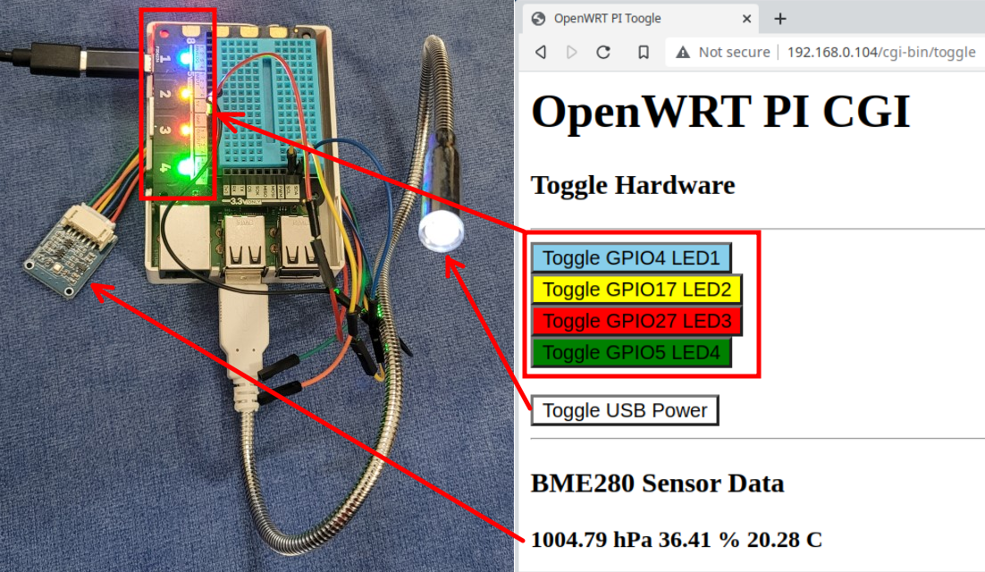
A Pi3 CGI Web Example
The hardware setup on this project used a Pimoroni Explorer HAT Pro. This Pi Top had four built-in coloured LEDs (on pins 4, 17,27 and 5). Before toggling a GPIO pin, the device needs to be defined and a direction needs to be set:
#!/bin/bash
#
# setgpio - setup GPIO
#
for pin in 4 17 27 5
do
  gpiodev=/sys/class/gpio/
  gpiodev+=$pin

  echo $pin | tee /sys/class/gpio/export
  echo "out" > /sys/class/gpio/gpio$pin/direction
done
ls /sys/class/gpio
For my Web Page, some buttons were used to pass a query string variable that is read at the top of the script before outputting the HTML. The BME280 sensor data is shown as a simple Bash variable.
#!/bin/bash
#
# toggle - Bash CGI to show some standard functions
#           -  toggle GPIO LEDs and USB power
#           - show some I2C sensor results
#      Note: GPIO pins need to be setup as outputs
set -e
# Toggle a pin if it's passed in the queue string
if  [[ "$QUERY_STRING" =~ "gpio" ]]; then
  pin=$QUERY_STRING

  # Read the GPIO pin value and then toggle it
  if [ "$(cat /sys/class/gpio/$pin/value)" == 1 ]; then
    echo 0 > /sys/class/gpio/$pin/value
  else
    echo 1 > /sys/class/gpio/$pin/value
  fi
fi

# Toggle USB power, ensure to add '&' for CGI use
if [[ "$QUERY_STRING" =~ "usb" ]]; then
  uhubctl -l 1-1 -p 2 -a toggle &> /dev/null
fi

# Get BME280 sensor data
data=$(read_bme280 --i2c-address 0x77)


echo "Content-type: text/html"
echo ""

echo "
<html>
<head>
<meta http-equiv='Content-Type' content='text/html; charset=UTF-8'>
<title>OpenWRT PI Toogle</title>
</head>
<body>
<h1>OpenWRT PI CGI </h1>
<h3>Toggle Hardware</h3>
<hr>
<button style='background-color:skyblue;'
   onclick='location.href=\"?gpio4\"'>Toggle GPIO4  LED1
</button><br>
<button style='background-color:yellow;'
   onclick='location.href=\"?gpio17\"'>Toggle GPIO17 LED2
</button><br>
<button style='background-color:red;'
   onclick='location.href=\"?gpio27\"'>Toggle GPIO27 LED3
</button><br>
<button style='background-color:green;'
   onclick='location.href=\"?gpio5\"'>Toggle GPIO5 LED4
</button><br><br>
<button style='background-color:white;'
   onclick='location.href=\"?usb\"'>Toggle USB Power
</button><br>
<hr><h3>BME280 Sensor Data</h3>
<b>$data</b>
</body>
</html>"

exit 0
Below is a picture of the web page and the Pi setup.
Summary
OpenWRT can breath a lot of life into old Raspberry Pi hardware. I’ve noticed a nice performance improvement on the old Pi hardware that makes the system quite usable.
Long term Raspberry Pi users may find OpenWRT’s lack of a pre-installed applications, drivers and no desktop a little frustrating at first.
It’s important to note that certain packages like Node-Red will take some work to get installed.
This blog only really looked at Raspberry Pi functionality under OpenWRT. I never documented some of the OS’s real strengths on the networking side.
Julia is a relatively new general purpose programming language that has an emphasis towards data science and AI.
In the past few year Julia has been gaining momentum, and it now ranks as the 20th most popular programming language. Like Python and R, Julia can also be used in Jupyter notebooks.
A Raspberry Pi module can be used as great platform to get introduced to Julia programming. Python users will be happy to hear that Python code can be integrated directly into Julia scripts.
In this blog, I’ll look at Julia GUI, micro-Web server, and charting apps that communicate with Raspberry Pi hardware. I’ll also introduce mixing Python code within Julia script to communicate with an LCD display.
Getting Started
Julia is supported on Windows, MacOS and Linux. See the download documentation for your specific system at : https://julialang.org/downloads/. The latest supported version of Julia can be installed on a Raspberry Pi with snap. To install snap:
Note, it’s possible to install Julia using: sudo apt install julia , however this will be an older version. To check the version of Julia either use the -v option, or simply run julia.
Your project setup will vary based on the sensors and hardware that you have available. For my setup I used a 16×2 LCD screen and a BME280 temperature/humidity/pressure sensor there were wired into the Raspberry Pi using I2C connections. The hardware was connected using a Pimoroni Explorerhat (~$25) which has four build-in colored LEDs and small prototyping breadboard.
The I2C (Inter-Integrated Circuit) protocol uses a multi-master/multi-slave serial communication bus, with the serial data line (SDA) on Raspberry Pi pin 3 and serial clock line (SCL) on pin 5.
Julia with Raspberry Pi GPIO
Communicating with the Raspberry Pi’s GPIO (General Purpose Input/Output) pins is done with the Julia PiGPIOpackage. This package can be installed at the command line by:
$ julia --eval 'using Pkg; Pkg.add("PiGPIO")'
To install and view status of packages within Julia:
julia> # load the Pkg module
julia> using Pkg
julia> # install a new package
julia> Pkg.add("PiGPIO")

julia> # view the status of installed packages
julia> Pkg.status()
Status `~/.julia/environments/v1.9/Project.toml`
  [bb151fc1] PiGPIO v0.2.0
Once this package is installed a daemon, pigpiodis created that the Julia script connects to. The pigpiod daemon can be started at the command line by: sudo pigpiod .
Below is some interactive code to; load the PiGPIO library, create the Pi object (p), set the mode of the pin, and finally write to and read from GPIO pin 17:
Note: adding a semi-colon at the end of a line will suppress debug information.
Now that the basic communications is working between Julia and the Raspberry Pi pins, GUI and Web server apps can be created.
GUI’s with Gtk
Like most programming languages Julia has a number of GUI options. For my testing I used the Gtk library which is installed in Julia by:
julia> using Pkg
julia> Pkg.add("Gtk")
Below is a Julia script to create a two button window that will turn on/off a GPIO pin. The Julia code looks somewhat similar to Python or Matlab syntax. Libraries are imported by the using command (lines 4-5). Functions are defined with a functionstatement and closed with an end (lines 32-35, and 38-41). A do block (lines 45-47) is used to group logic with a function.
#
# gtk_17.jl - Use a Gtk GUI to toggle a PI GPIO LED
#
using Gtk;
using PiGPIO;

# Setup GPIO
p=Pi();
led_pin = 17;
set_mode(p, led_pin, PiGPIO.OUTPUT)

# Init GUI objects
win  = GtkWindow("Toggle a Pi LED", 300, 300);
g  = GtkGrid();

# Text label
label  = GtkLabel(string("Pin : $led_pin"));
# Buttons
btn_on  = GtkButton("ON");
btn_off  = GtkButton("OFF");

# Put GUI widgets into a grid
g[1:2,1] = label;   # Cartesian coordinates, g[x,y]
g[1,2] = btn_on;
g[2,2] = btn_off;

# Show the GUI Window
push!(win, g);
showall(win);

# Callbacks
function turn_on(w1)
	PiGPIO.write(p, led_pin, PiGPIO.HIGH)
	println("ON button pressed")
end
signal_connect(turn_on, btn_on, "clicked")

function turn_off(w2)
	PiGPIO.write(p, led_pin, PiGPIO.LOW)
	println("OFF button pressed")
end
signal_connect(turn_off, btn_off, "clicked")

# Close cleanly
signal_connect(win, :destroy) do widget
    Gtk.gtk_quit()
end
Gtk.gtk_main()
This Julia script is run by:
$ julia gtk_17.jl
Below is a picture of the Julia Gtk app toggling GPIO pin 17 (the yellow LED 2 on the Pi Explorer Hat).
Julia Web Server
Like graphic libraries, there are a few web server options. I found that the Genie web frame work was one of the easiest to get up and running.
Below is an example web app that create two button to turn a GPIO pin on/off.
For this script, three libraries are used; Genie, for the web server, Sockets, to get the Raspberry Pi’s IP address, and PiGPIO, to connect to the GPIO pins (lines 4-6). Pin 17 is set as an output in lines 9-11. To keep things simple the HTML code is defined as a variable (lines 19-32). For larger projects it would be recommended that external HTML files be used.
The Julia code defines three routes (lines 34-49). The first route is the default (/) page that prints out the html_file variable. The /ON and /OFF routes set the GPIO pin output when either the ON or OFF form buttons are pressed.
The final line in the script sets up the web framework to run on port 8001 with the Raspberry Pi’s IP address.
#
# web2gpio.jl - Julia Web Page with routes to turn on/off a Pi GPIO pin
#
using Genie
using Sockets # to get IP address
using PiGPIO;

# Setup GPIO
p=Pi();
led_pin = 17;
set_mode(p, led_pin, PiGPIO.OUTPUT)

# get the Rasp Pi IP address
myip = string(getipaddr() )

println("Loading Genie...")

# create an HTML document
html_file = """
<html>
<head>
<title>Julie GPIO Test Page</title>
</head>
<body>
  <h1>Toggle PI LED</h1>
  <form>
    <button type="submit" formaction="/ON">ON</button>
    <button type="submit" formaction="/OFF">OFF</button>
  </form>
</body>
</html>
"""

route("/") do
  return html_file
  println("Connected")
end

route("/ON?") do
  PiGPIO.write(p, led_pin, PiGPIO.HIGH)
  return html_file
  println("ON Selected")
end

route("/OFF?") do
  PiGPIO.write(p, led_pin, PiGPIO.LOW)
  return html_file
  println("OFF Selected")
end

# Start the web app on port 8001
up( 8001, myip, async = false)
To start the Julia web script enter:
julia web2gpio.jl
Plot BME280 Sensor Data
For this final example the goal is to create a dynamic bar chart that will show BME280 temperature and humidity data.
The Plots charting library is installed by:
julia> using Pkg
julia> Pkg.add("Plots")
Unfortunately Julia does not have a large Raspberry Pi sensor library like either Python or Node-Red, so for this a BME280 Bash command line utility can be used:
$ # Install a Python based Bash command line tool
$  sudo python -m pip install bme280
BME280 sensors typically use I2C addresses of 0x76 or 0x77. The i2cdetect tool can be used to verify which address your sensor is on ( i2cdetect -y 1) .
Within Julia, external command strings are define with backticks ( ` ). Below is an example that creates a command variables (mycmd), then checks the variable type and runs the command:
julia> mycmd = `pwd`;   # pwd=present working directory
julia> typeof(mycmd)
Cmd

julia> run(mycmd) ; # run the command
/home/pete/jtest
The Julia read function can run an external command and store the output string as a variable. A split can be used to output BME280 results into an array strings. Below is some interactive code that show the humidity as the 3rd index (data[3]), and temperature as the fifth index (data[5]).
The Julia script below has a while loop that cycles every 10 seconds (lines 9 and 28). The sensor data is read from the Bash command and then passed to a data array (lines 12 and 13). The temperature and humidity values are parsed as floats (lines 16 and 19) and then shown in a bar chart (lines 23-25).
#!/snap/bin/julia
#
# bme_280.jl - show BME280 sensor data on a refreshing bar chart
#
using Plots
using Dates

print("Show BME280 readings every 10 seconds. Control-C to exit.\n")
while true

    # get the sensor output, then split it into an array of strings
    output = read(`read_bme280 --i2c-address 0x77`, String)
    data = split(output)

    # get the temperature as a Float, (5th item in array)
    t = parse(Float64,data[5])

    # get the humidity as a Float, (3rd item in array)
    h = parse(Float64,data[3])

    # define a bar chart
    thetitle = "BME280 Data - " * Dates.format(now(), "H:MM:SS")
    p = bar(["Temperature (C)","Humidity (%)"], [t,h],legend=false,
            title=thetitle, texts = [t,h], color=[:red, :yellow] )
    display(p)

    sleep(10)
end
This script has the location of the julia binary in the first line, so the file can be run like a Bash or Python application:
$ # enable the execute status on the file
$ sudo chmod +x bme_280.jl
$ # run the script directly
$ ./bme_280.jl
Julia calling Python
One of the interesting features of Julia is that script languages like Lua, Matlab, R and Python can be integrated directly into Julia code.
To enable this functionality the first step is to install the required language library. To add the Python interface library:
$ julia --eval 'using Pkg; Pkg.add("PyCall")'
Most of the Raspberry Pi sensors and 3rd party devices are supported in Python, so the PyCall library can come in extremely handy when you want to communication with any external Pi hardware.
An easy example using PyCall can be done with a 16×2 LCD display. The first step in the integration is to install the Python Pi LCD library:
$ # install the Python Raspberry Pi LCD library
$ pip install RPi.bme280
PyCall works in a couple of different ways. The first is that Python code can be used directly within Julia script, and the second approach is to have Julia code reference Python objects.
An example to run Python code directly to write text to a 2 line I2C LED screen:
julia> using PyCall
julia> py"""
       # Use Python to write text to a 2 line LCD screen
       from rpi_lcd import LCD
       lcd = LCD()
       lcd.text('Hello World!', 1)
       lcd.text('Raspberry Pi', 2)
       """
julia> # Now back into Julia
The py statements runs a string of multiple Python lines. Errors will occur if the string does not adhere to Python’s indentation rules.
To do the same functionality referencing a Python object in Julia:
using PyCall
rpi_lcd = pyimport("rpi_lcd");
lcd = rpi_lcd.LCD();
lcd.text("Hello from Julia", 1)
lcd.text("Raspberry Pi!", 2)
Summary
A Raspberry Pi can be a good platform to get introduced to Julia programming. For Python user the mixing of Python code into Julia scripts allows for common Pi hardware to be integrated into your new projects.
After getting a handle on some of the Julia basics, the next steps might be to investigate data analysis, Jupyter notebooks, or AI applications.
It should be noted that playing with Julia on older Raspberry Pi hardware or using early versions of Julia can run painfully slow. To improve the call-up time, Julia offers a number of packaging and pre-compilation options.
I wanted to introduce my daughters to using PHP on Raspberry Pi Projects. My goal has been to try and keep things super minimalist so that they can quickly pull together a project for school without being overwhelmed with installation or dependency issues.
In this blog I will look at:
Running a 1-Line PHP server (no other web server will be used or installed)
Show Bash diagnostics tools on a PHP page (3 lines of PHP)
Use a PHP calls to read/write Rasp Pi GPIO pins
Loading and Running a PHP Server
Typically PHP is loaded with Web server applications like Apache, but PHP can be run as a standalone application. To install PHP on a Raspberry Pi or Ubuntu system:
sudo apt-get install php -y
The syntax to run PHP as a standalone web server:
php -S <addr>:<port> [-t docroot] startpage

# for example
php -S 192.168.0.111:8080 mypage.htm

# to use Bash to get your IP
php -S $(hostname -I | awk '{print $1 ":8080"}') mypage.htm
It’s important to note that the standalone PHP server is designed for testing and very small projects. It should not be used for any kind of production environment.
Superquick PHP Primer
PHP is an extremely popular Web programming language.
PHP originally stood for : Personal Home Page, but after a lot of enhancements it now stands for: “PHP: Hypertext Preprocessor”.
A PHP file normally contains HTML tags, and some PHP scripting code. A PHP script starts with “<?php” and ends with “?>“. An example would be (test1.php) :
<!DOCTYPE html>
<html>
<body>

<h1>A PHP Test Page</h1>

<?php
// This is PHP script block
$a = 4;
$b = 6;
echo "Hello World! ";
echo "4 x 6 =" . ($a * $b);
?>
<p>Below is a single line of PHP</p>
<?php echo "This is a single line" ?>

</body>
</html>
To learn about the PHP syntax there are some good references.
It’s useful to know that PHP code can be run directly with the PHP interpreter:
# A single line of PHP (note: -r for single line)
$ php -r '$a=4; $b=5; echo  $a * $b . "\n" ; '
20

# Run a PHP script
$ php test1.php

<!DOCTYPE html>
<html>
<body>

<h1>A PHP Test Page</h1>

Hello World! 4 x 6 =24<p>Below is a single line of PHP</p>
This is a single line
</body>
</html>
Command line Diagnostics on a Web Page
Linux command line utilities can have their output viewable on a Web page. The example below (vmstats.php) uses the PHP shell_exec call to execute the vmstat command line utility and the results are echoed to the web page. The <pre> tag is used to present the results in fixed-width font.
<?php
// vmstats.php - A PHP test page to some CPU stats
echo "<pre>";
echo shell_exec('vmstat');
echo "</pre>";
?>
A 1 line PHP web server command to call this page is:
There are a few ways to access the GPIO pins in PHP: 1. use a PHP library 2. shell to the gpio command
Using a PHP library allows for a standard PHP interface, with an object model.
However from testing I found that the PHP libraries were not as flexible as the standard gpio command. For example you could not access extended GPIO pin numbers (i.e. 200).
GPIO Command Line Utility
PHP can shell out to thegpiocommand line utility. I liked this approach because I could test the actions manually before putting them into a PHP web page.
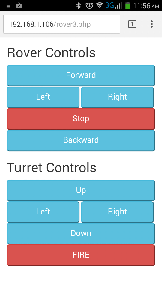
The Raspberry Pi rover project is a good example that pulls together:
Control of Pi GPIO pins
PHP Forms
Cascading Style Sheets (CSS) for mobile phone presentations
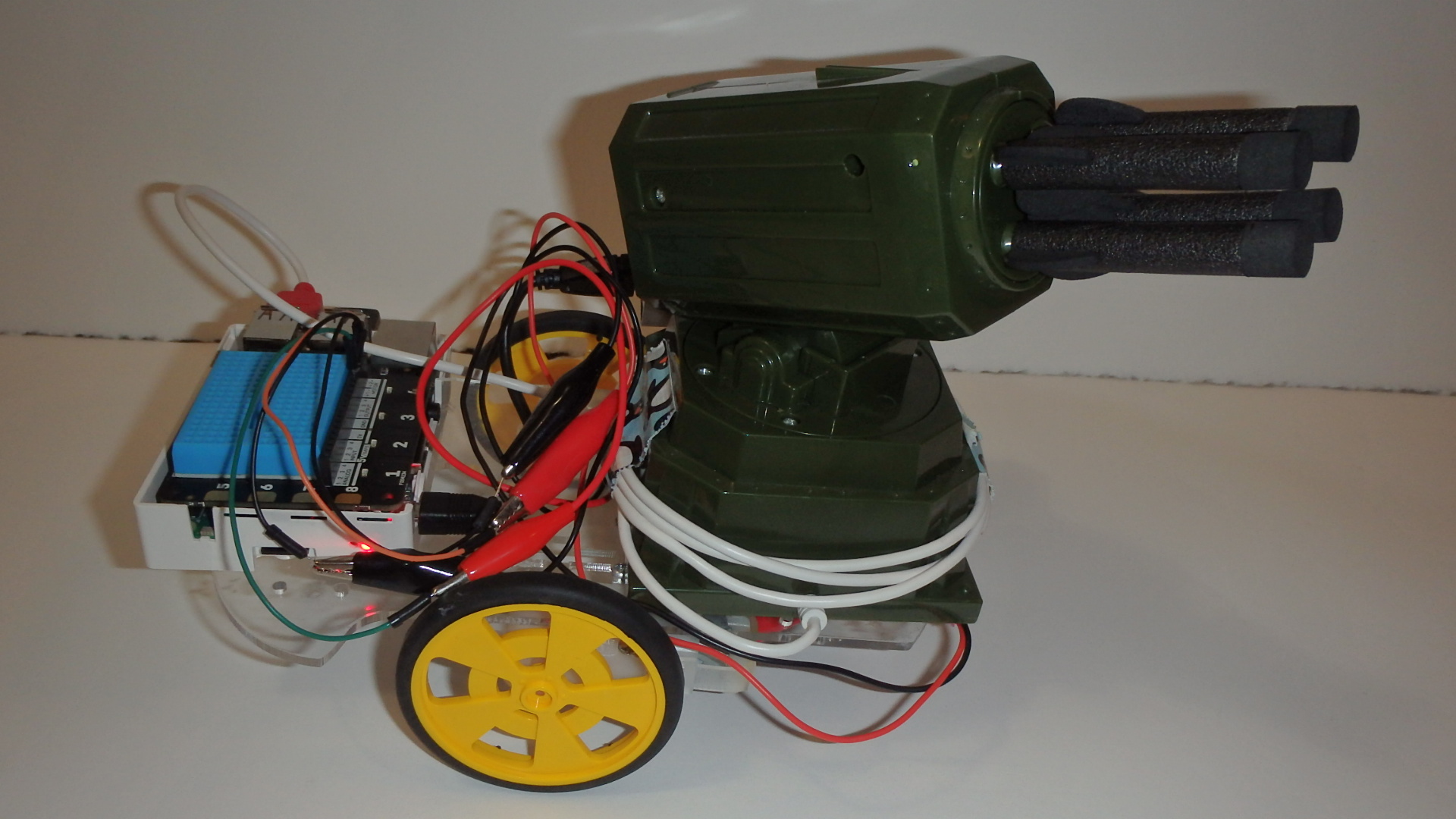
Motors should not be connected directly to a Raspberry Pi because they could potential damage the Pi hardware. It is recommended that some intermediate equipment or a motor top be used. For this project we used a Pimoroni ExplorerHat Pro.
PHP Forms
This example uses an HTML post method that is defined in the <form> tag. The buttons pass the values of: go, stop, left and right.
The PHP code look for the post value and then does a gpio write for the required action. For example a go will turn on both GPIO motor pins.
There are quite a few good mobile templates to choose from. Bootstrap (http://getbootstrap.com/) is one of the most popular frameworks, and for Pi applications it seems to be a good fit.
Some of the key items are:
Add references in to the bootstrap ccs and js files
Add tags with the required class definitions:
the btn-lg class will make a large button, instead of standard sized btn
different button colours are possible using btn-info, btn-success. btn-danger
Button width is defined with style=”width: xx%” . For multiple buttons the sum of the width needs to <100%
Further Examples
Below are some pictures of a mobile rocket launcher project. The Web page had two sections. The top section controlled bi-directional motors that were connected to a Explorer HAT Pro shield. The bottom section controlled the rocket launcher turret. The missile launcher was connected via a USB cable to the Pi.
This Bash statement echo’s to port 8080, the output is an HTTP header with the file content length defined. The cat command is used to show the HTML file.
This 1 line Bash example shows a single page (index.htm) which isn’t overly useful, there are other web server options that would work much better.
Where a Bash web server really stands out is in its ability to execute command line utilities or scripts and send the results to a web client.
Bash Web Server Calling Bash Commands
The output from command line utilities like iostatcan be sent directly to a web client:
while true;
  do echo -e "HTTP/1.1 200 OK\n\n$(iostat)" \
  | nc -l -k -p 8080 -q 1;
done
There are 2 important options that need to be set on nc, and they are: -k (this keeps the connection open after the first connection) and -q 1 (this closes the connection after 1 seconds, so another connection can occur). Depending on the complexity of the script that is used the -q timing may need to be adjusted.
The web page for the iostat command will look like:
Multiple Commands with Headings
Comments and multiply command line utilities can be defined as a variable that can be passed to the Bash Web server.
The figlet utility can be used to create custom ASCII headings, this is useful if you want to keep things simple without using HTML syntax. To install figlet in Ubuntu enter: sudo apt-get install figlet .
An example of using figlet headings and the sensors and vmstat utility is:
title1=$(figlet Sensors)
cmd1=$(sensors | sed -e 's/\°/ /g') # browser has problem with degrees, so remove
title2=$(figlet VMStat)
cmd2=$(vmstat)
thebody="$title1\n$cmd1\n$title2\n$cmd2"

while true;
  do echo -e "HTTP/1.1 200 OK\n\n$thebody" \
  | nc -l -p 8080 -q 1;
done
Bash Web Server with Raspberry Pi GPIO
For many Raspberry Pi projects monitoring the status of the GPIO (General Purpose Input/Output) pins is quite important.
The Raspberry Pi gpio utility can be used to show the present status with the readall option:
Rather than passing the Bash commands as a string, a small Bash script (web_body.sh) file can be created. This file will show the time and then call the gpio readall command.
#!/bin/bash
# web_body.sh - Show the time and PI GPIO pins

date $T

echo "$(gpio readall)"
The online Bash web server command is:
while true; do { \
  echo -ne "HTTP/1.1 200 OK\r\n"; sh web_body.sh; } \
  | nc -l -k -q 2 8080; \
done
The Web page for this script will look something like:
Send GPIO Writes from the Address Bar
Client side GET requests can be simulated on the browser address bar.
For example entering gpio write 7 1 on the address bar sents the Bash Server a GET request.
The HTTP request encodes spaces, so a space appears as a %20.
Bash code can be added to look for specific messages. In this case the “gpio write 7 1” or “gpio write 7 0” message can be search for, and if it is found then that exact message can be executed.
The Bash code can now be modified to ; look for the “GET gpio” message, then decode any HTTP %20 characters to spaces, next parse out the string to get the gpio message, and finally execute the required command. The code is below:
while true;
  do { echo -ne "HTTP/1.1 200 OK\r\n"; sh web_body.sh; } | \
  nc -l -k -q 5 8080 | grep "GET /gpio" | \
  sed -e 's/%20/ /g' | \
  eval $( awk '{print substr($0,6,15) }') ;
done
With the new code, the gpio write is executed and the result can be seen in the web page.
Create an HTML Form
Entering commands on the command line works but it’s crude, a better way is to create an HTML Form.
The Bash web server code can remain exact the same as in the earlier example.
The original script (web_body.sh) file can be modified to made the output HTML format and three forms can be included. The first and second form will define the GET actions to turn on or off the GPIO pin and the third form will be used to refresh the page to check for GPIO changes.
#!/bin/bash
# web_body.sh - Show the time and PI GPIO pins
#             - Use HTML instead of text output
#             - Add forms for GPIO on/off, and a refresh
echo "
<!DOCTYPE html><html><head>
</head><body>
<h1>Bash Commands in a Web Page</h1>
<h2>Toggle Pin 7 On/Off</h2>
<form action='gpio write 7 0'>
 <input type='submit' value='OFF'>
</form>
<form action='gpio write 7 1'>
 <input type='submit' value='ON'>
</form>
<form action=''>
 <input type='submit' value='Refresh Page'>
</form>
<pre>
"

date $T

echo "$(gpio readall)"

echo "</pre></body></html>"
The client web page is now:
After turning on or off the GPIO pin, a refresh of the web page is required to see the new status.
Final Commands
A Bash Web Server is a quick and easy solution for viewing the output from Bash scripts and commands. I especially like the fact that I don’t need to install any special software and I don’t need to write any HTML code.
It is important to note that the number of concurrent connections is very low, (1/sec if the nc -qoption is 1).
A Bash Web Server supports client side GET and POST requests, however for complex requirements the Bash code could start to get messy quickly and it would probably be best to look at another solution.
There are some great communication protocols (MQTT, RabbitMQ, ReDis …) that are excellent for passing data between nodes.
For applications where you only need to do simple communications a couple of lines of Bash can be used with TCP or UDP sockets.
In this blog I wanted to document UDP/TCP communications using Linux Bash commands to:
define periodic 1-way communications
use progress bars to show data from remote nodes
remotely send commands to a Raspberry Pi
setup simple TCP backdoors
NC (NetCat) – for TCP and UDP Connections
In theory you should be able to create a input read via something like:
echo $(read < /dev/udp/127.0.0.1/9999)
Then do a write using:
echo "some text" > /dev/udp/127.0.0.1/9999)
Unfortunately Linux device connections are not fully reliable, especially on the read or listening side. However the write component appears to be fairly solid. Luckily there is a solid solution using the nc (NetCat) command line utility. The nc utility is typically preloaded on most Linux systems.
The nc utility supports both UDP (-u option) and TCP (default) connections.
To setup a UDP listener, use the IP address of the listener node, and select the -k option to allow multiple connections to occur:
nc -u -l -k 192.168.0.111 9999
For this example the listener’s IP is: 192.168.0.111, and port 9999 is used.
To do manual writes from the command line, enter:
nc -u 192.168.0.111 9999
To send data from a script there are two methods, either using nc or writing to the device:
# writing via nc, -w0 send only 1 message
echo "456" | nc -u -w0 192.168.0.111  9999
# writing via device:
echo "456" > /dev/udp/192.168.0.111/9999
Multiple Writes and Zenity Progress Dialogs
Zenity is command line dialog utility that is typically preinstalled on most versions of Linux.
The data that is sent to the UDP listener can be piped to Zenity progress bar:
When the script echos an integer the progress bar will be updated with the integer value. An echo string starting with a “#” will update the text above the bar.
The progress bar is from 0-100%, but the integer value can be re-scaled to make the information clearer. For example to re-scale 0-60 secs to 0-100:
YAD (Yet Another Dialog) is a command line GUI utility that offers a little more functionality than Zenity. To install YAD on Raspberry Pi’s and Ubuntu: sudo apt-get install yad
A bash command with a UDP listener with YAD 2-bars would be:
nc -u -l -k 192.168.0.111  9999 | yad --multi-progress \
  --bar="CPU Idle" --bar="CPU Temp" --title="Remote CPU Info"
The CPU Idle Time can be found by:
top -n 1 | grep %Cpu | awk '{print $8}'93.8
The CPU Temperature on a PC can be found by:
sensors | grep CPU | awk '{print substr($2,2,4)}'44.0
A script to send the CPU Idle Time and Temperature to the UDP listener is:
For YAD multiple progress bars, an echo of 1: is for bar 1,2: is for bar 2 etc. Echo-ing “2:# ” updates the text for the 2nd bar.
NC is not the same on Rasp Pi
I found that on the Rasp Pi the nc listening functions would not pass any information to bash scripts. Manual mode still works to view messages, but the messages can’t be piped to other commands.
This mean that things like the Zenity and YAD progress bars would not work on a Raspberry Pi. For many applications this may not be a big problem because the Rasp Pi can still send information via nc.
NC vs. NCAT
The ncat utility is very similar to nc but it offers the ability to run commands. By default nc is preloaded on most systems, but ncat needs to be installed. Installing ncat will vary based on your OS.
The ncat utility allows you to make backdoors so be careful of its use.
To create a backdoor simply (via TCP), define the ncat -c (execute command option) to be /bin/bash:
ncat -l -k 192.168.0.108 9999 -c /bin/bash
If on a remote node you enter: ncat 192.168.0.108 , you can start typing commands that are run on the remote node with the results echoing back. Very cool for test system but super dangerous for real systems.
Remotely Toggle a Rasp Pi GPIO Pin
Rather than opening up the system totally fixed commands can be defined. For example to toggle pin 7 on a Rasp Pi. A listener script is run:
ncat -l -k 192.168.0.108 9999 -c "gpio toggle 7"
A remote button GUI script could be used in conjunction with the listener script to toggle the GPIO pin:
#!/bin/bash
#
# Toggle a Rasp Pi GPIO pin

rc=1 # OK button return code =0 , all others =1
while [ $rc -eq 1 ]; do
  ans=$(zenity --info --title 'Remote Connect to Pi' \
      --text 'Toggle GPIO Pin' \
      --ok-label Quit \
      --extra-button TOGGLE \
       )
  rc=$?
  echo "${rc}-${ans}"
  echo $ans
  if [[ $ans = "TOGGLE" ]]
  then
        echo "Toggle Pin"
        nc -w0 192.168.0.108  9999
  fi
done
Send a Command String to Run Remotely
For this example the Rasp Pi is setup to be TCP listener, and the command (-c option) is /bin/bash, so this allows the remote PC to send custom commands:
ncat -l -k 192.168.0.108 9999 -c /bin/bash
On the remote system a bash script is created with 2 buttons and the custom commands are sent to the Pi to run:
#!/bin/bash
#
# Toggle two Rasp Pi GPIO pins

rc=1 # OK button return code =0 , all others =1
while [ $rc -eq 1 ]; do
  ans=$(zenity --info --title 'Remote Connect to Pi' \
      --text 'Toggle GPIO Pins' \
      --ok-label Quit \
      --extra-button Pin2 \
      --extra-button Pin7 \
       )
  rc=$?
  echo "${rc}-${ans}"
  echo $ans
  if [[ $ans = "Pin2" ]]
  then
        echo "gpio toggle 2" | nc -w0 192.168.0.108  9999
  elif [[ $ans = "Pin7" ]]
  then
        echo "gpio toggle 7" | nc -w0 192.168.0.108  9999
  fi
done
On systems other than Rasp Pi, the nc command can also be used to run remote programs by:
In this blog I’ve kept things focused on TCP/UDP communications with bash script but you could easily include Arduino, Python and Node-Red as either clients or servers.
cowsay – generates ASCII pictures of a cow (or other animals) with a message
jp2a – a small utility that converts JPG images to ASCII.
I this blog I wanted to document some of the things that I found and how these utilities could be used in a ncurses program.
Cowsay
Cowsay has been around in the Linux world since 2007. It is now available in Windows and Android. To install cowsay in Linux or a Rasberry Pi :
sudo apt-get install cowsay
Coway takes text messages that you pass it.
~$ cowsay "I'm not worried about mad cow...because I'm a helicopter"
 _________________________________________
/ I'm not worried about mad cow...because \
\ I'm a helicopter                       /
 -----------------------------------------
        \   ^__^
         \  (oo)\_______
            (__)\       )\/\
                ||----w |
                ||     ||
If you install the Linux fortune app (sudo apt install fortune) you can pass random fortune messages:
~$ fortune | cowsay
 _______________________________________
/ You get along very well with everyone \
\ except animals and people.            /
 ---------------------------------------
        \   ^__^
         \  (oo)\_______
            (__)\       )\/\
                ||----w |
                ||     ||
There are a number of different images that can be used. To see the list of what is available:
In my Python curses app I read the eyes.txt file and used the stdscr.addstr method to write it to the screen. (Note: For more info on writing Python/C curses or Lua curses)
# c_eyes.py - create a curses with a cowsay message
#
import curses , time, random

# create a curses object
stdscr = curses.initscr()
height, width = stdscr.getmaxyx() # get the window size

# define two color pairs
curses.start_color()
curses.init_pair(1, curses.COLOR_RED, curses.COLOR_WHITE)
curses.init_pair(2, curses.COLOR_YELLOW, curses.COLOR_BLACK)
curses.init_pair(3, curses.COLOR_BLUE, curses.COLOR_BLACK)

# Read the cowsay output file and write it to the screen

f = open("eyes.txt", "r")
eyes = f.read()
stdscr.addstr(0, 0, eyes,curses.color_pair(3))

# Add a footer
stdscr.addstr(height-1, 0, " " * (width-1),curses.color_pair(1))
stdscr.addstr(height-1, 0, " Key Commands : q - to quit " ,curses.color_pair(1))

# Add intrusion code here....
stdscr.addstr(15, 5, "PIR1 input: no movement" ,curses.color_pair(2) )
stdscr.addstr(16, 5, "PIR2 input: no movement" ,curses.color_pair(2) )

curses.curs_set(0) # don't show the cursor
stdscr.refresh()

# Cycle to update text. Enter a 'q' to quit
k = 0
stdscr.nodelay(1)
while (k != ord('q')):
    k = stdscr.getch()

curses.endwin()
jp2a – converts JPG images to ASCII
jp2a is a Linux utility that is installed by:
apt-get install jp2a
I found that you’ve got to be selective of the jpeg image that you are trying to convert an example of a castle:
jp2a castle.jpg --colors --background=light
Old fairytale castle on the hill isolated on white. 3d illustration.
Another example was to convert a flag. For this example I found the width option to be useful: